Final Year Project Update, Boards
I’ve been putting off writing here for a few weeks, which is several weeks longer than I had hoped. Originally the plan was to talk about not only the completed, commercial development boards I had received, but also the status of my Final Year Project at my University. Every day I’ve been trotting down to the letter box like an over excited puppy, only to be greeted with bitter disappointment (and, in the case of last night, a rather unhappy cricket). I’m not sure if we’re in a package drought, or if the boards have been lost, eaten by a Grue, or circling Belgium like my poor old Dragon did but in any case, I’m unhappy since it’s thrown my schedule out of whack.
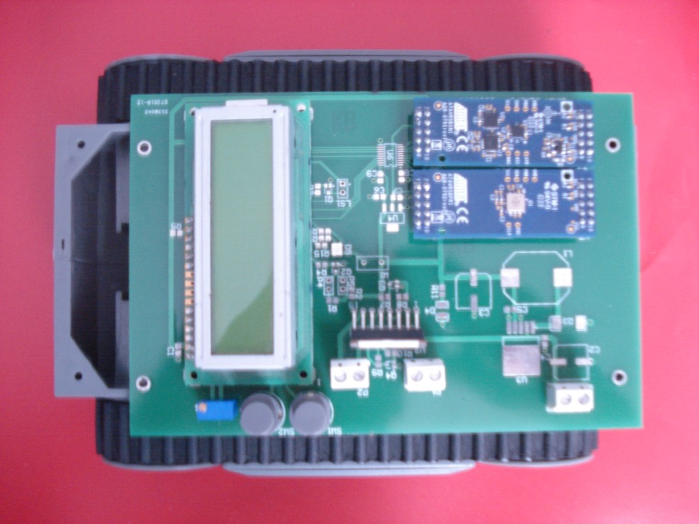
By taking the original board revision – that I managed to mess up most excellently, neccesitating the need of the second board revision – I can however apply the old saying “fake it until you make it” quite literally and provide a mockup of the system. Here is a picture of the main through-hole components inserted into the faulty first revision PCB so you can get a feel of the design:
Which should be quite close to the final construction (barring some spacers, components and a butt-load of solder. There you can see the two Atmel Inertial One and Pressure One sensor boards, H-Bridge IC, 16×2 Alphanumeric LCD and control buttons. Not shown here is the main processor for the system, which is actually mounted – or at least, will be mounted – on the board underside beneath the LCD screen for space and routing reasons. I do hope the actual board turns up soon, since I’m itching to get this thing built and ready for development.
As I mentioned in my Twitter feed a few days ago, the last of the parts have arrived for the new revision PCB, and good lord are some of them small. Last year I hand-soldered a FTDI FT232 IC which was in a 12 mil package pitch, and that was hard work even with a fine-pitch iron and a 10x magnifying stereo microscope. This time I’ve got two different level translator ICs – and one of them (PCA9306 I2C level translator) is in a US-8 package. Yes, 2mm by 3mm. It’s time for me to start making friends with the University workshop staff, since I’ve heard they have a re-flow oven and solder paste.
A couple of days ago I got impatient enough to start coding for the project, as my time is quickly running out. So far I’ve only written the hardware drivers and the main application test jig, with the Bluetooth stack yet to write, but it means that everything should be ready for heavy development once it’s soldered up. I’ve decided to make the application support both HID and Bluetooth USB classes, so that (for testing purposes) the robot can be controlled with an attached USB joystick or mouse, or remotely controlled and monitored wirelessly if a Bluetooth adapter is inserted. That should give me something to show off early before the really hard code is completed, while also acting as a good test for the board hardware.
Right, so on to the other hardware I’ve received. First up is related to the above – the new Micropendous-A boards, now in production from Opendous Inc:
This is a new revision of the older Micropendous-3 boards, with a slightly altered design. Most notable is the lack of a second USB connector; rather than using separate device/host USB connectors and a switching IC, Matt’s instead decided to keep a single USB-A plug to keep things simple, with a separate Female-to-Female USB adapter for hosting devices. You’ll notice here that my sample is actually the reverse, with a female plug on the board, but after I pointed out the dangers of a USB Male-to-Male adapter and due to availability problems, the genders have been reversed. This actually works out in my favour, since I need this specific board for my project, and I only plan on performing USB host duties.
The neat thing that’s got me excited about the board is that is is AT90USB1287 based, which means USB hosting. Since the PSGroove PS3 hack cleaned out the world’s supplies of USBKEY boards, there hasn’t been a suitable replacement for USB hosting which is a darn shame. Having an external 128KB SRAM and a 16MHz crystal on a board with USB hosting abilities means that people can finally get around to making USB host projects again. Kudos to Matt for the excellent board design.
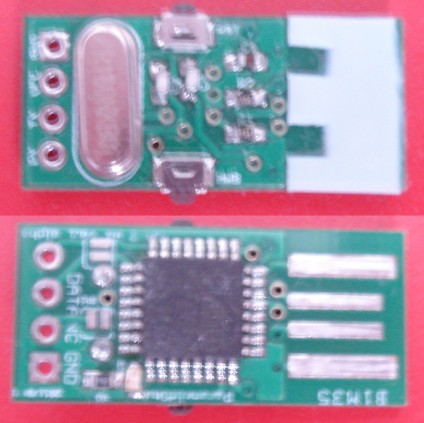
Also in my grab-bag of goodies is the USB2-AX, a tiny board containing an ATMEGA32U2 microcontroller:
Which was surprisingly hard to photograph right, due to its diminutive size. Here we can see the technique used on many cheap USB peripherals today – the PCB “finger” style connector rather than a real USB connector, which helps cut down on the overall board size. Designed as a servo motor controller, this board has a LED, user button and the USART pins mapped out and so can be used for multiple purposes. I must admit that the first thought that crossed my mind was making one of these with it, but then I thought of a mail and message indicator. I’ve shelved that for now however, as I can’t find a suitable API for my email or IM clients, and I’m convinced that XChat’s scripting system is nothing more than an urban legend.
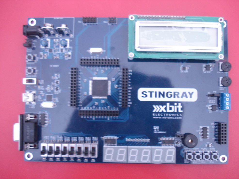
Finally today is the Xbit Electronics Stingray XMEGA development board. This is getting a full review very soon, since I’ve had it a while and I’m starting to feel rather guilty about not putting one up sooner. A public promise to myself; the next post I do will be a full review. Here’s a teaser photo:
Oh and those mid-year exams? Aced them.


The 0.5mm pitch package should not be a real problem, just trust in yourself. 🙂
On professionally manufactured boards with solder-stop it is very easy to remove shorts with desoldering wick. Actually, some people use wide solder tips to provide enough heat very fast, thereby intentionally shorting the pins.
Then they remove excess solder; what is left behind after applying the desoldering wick is easily enough to fulfill its duty.
Good luck!