The Mass Storage Layers
Plenty of people have been asking around on AVRFreaks for information on making a device which is capable of showing up as a removable storage device under Explorer, so that images or logs can be downloaded with any modern operating system. What these people do not know is that the creation of a device is quite a complex task, involving several “layers” which must be correctly implemented before it will work correctly.
I’m taking a break from my usual boring blogs to try to make the inner workings of such a device a little less of a mystery.
First, let’s look at the six different layers required for a typical mass storage device:
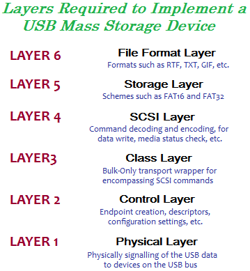
The MyUSB Mass Storage Device demo only implements layers 1 through 4. This is because the demo is for a “dumb” storage device, in that all it does is expose a readable/writable storage medium for the host OS. The host’s OS is free to use whatever storage scheme it sees fit to format the device, which is why the demo disk can be formatted to any scheme desired by the user. The device itself never tries to create files on the disk, so the last two layers are unnecessary.
Now, let’s look at the different layers in a little more detail.
LAYER 1 – PHYSICAL LAYER:
The physical layer is the lowest level layer of USB, and is the protocol dictating the exchange of data between a USB host, and one or more devices present on the USB bus. It provides a means of detecting when devices are added or removed, and for data transmission to an addressed device. The AT90USB series AVR microcontrollers include a full USB controller, which takes care of the entire layer 1 for us, allowing us to interact on the physical layer via a group of exposed USB control and status registers.
The physical layer is generally not of any concern to embedded developers, unless of course it is being bit-banged or otherwise generated (as is the case with the software-only USB implementations for some AVR models available on the web) without the aid of a dedicated USB controller.
LAYER 2 – CONTROL LAYER:
Layer 2 is the layer which handles all the device-level requests. This layer controls the creation and modification of the endpoints in a device, the processing of device control commands – including class-specific control commands – and the fetching of the device’s “descriptors” (structures containing information for the host about the device’s capabilities, features, implemented classes and power requirements) for the host
MyUSB handles the control layer transparently, only handing of the processing of such requests if they are class-specific commands rather than general device commands. In the case of the Mass Storage class, there are special control commands for the resetting of the storage device, and for the retrieval of the number of LUNs (Logical UNits, logical disks in the device).
LAYER 3 – CLASS LAYER:
This layer is specific to each implemented class. The USB specification provides the general USB communication specification, and is completely function-agnostic. Each device may implement one or more of the standard “classes” defined by the USB organization. In the case of these defined classes, the method of data transfer inside the class is also defined.
For the Mass Storage class, there are two schemes for data transfer – CBI (designed for floppy drives) and the Bulk-Only transport specification. The Bulk-Only transport is the one that is the most used, and specifies how commands and data to/from the host should be wrapped up in a well-defined manner to provide error tolerance.
LAYER 4 – SCSI Layer:
Up until now, all the layers have been completely USB-specific. However, the Mass Storage class calls for the actual medium commands (for reading, writing, status checking and the like) to be standard SCSI commands. This means that the USB transport is really just one giant wrapper for a SCSI drive – something made obvious on Linux platforms, where the kernel messages indicate a virtual SCSI driver being initiated when a USB Mass Storage device is inserted.
Once commands have been removed from the Bulk-Only wrapper, they are passed through the SCSI decoder. The SCSI layer then performs the required actions on the physical medium, resulting in data being read or written from the disk.
LAYER 5 – STORAGE LAYER:
Layers 5 and 6 are optional, and are only required if the USB device wishes to manipulate the data on the disk so that the host can read it (typical for data loggers, digital cameras and the like). This layer is able to decode the file system of the disk, so that files and folders can be added, deleted, renamed or otherwise manipulated. Because embedded devices contain limited resources, typically only one file system is supported, forcing the host to use the same file system to prevent corruption. For this reason, Mass Storage MP3 players, cameras and other devices are typically locked into using the easy to program and for and royalty free FAT file system.
LAYER 6 – FILE FORMAT:
Layer 6 is the easy one, and just entails being able to write data to the file system in the file format of choice. Loggers normally save in simple ASCII files, which require no file structure, although more complicated devices such as digital cameras need to be able to write to an image format such as JPEG.
And there you have it – a basic overview of the different layers required for a USB Mass Storage device. Hopefully this will be of some interest to embedded engineers interested in learning the USB specification.

